Capiche 140 Rebuild
By Iain Jeffrey
I’ve been asked to do a ‘Rebuild’ piece for the club website with regard to my Capiche 140 model after an unfortunate incident at Blyth flying field which resulted in a written off model.
I had been flying for approximately 15 minutes and over flew the strip to start the landing circuit, as I turned over the trees at the western end of the strip the model pitched nose down with no up elevator response, sending it straight into the unforgiving trees at speed. I was a little concerned to say the least as it puts questions in your mind, was it pilot error or radio! Myself and a couple of club mates went looking for it and found it stuck in a tree not quite making it to the ground saving it from major frontal damage, I was glad of the help (thanks again guys) as the model was in a number of pieces.
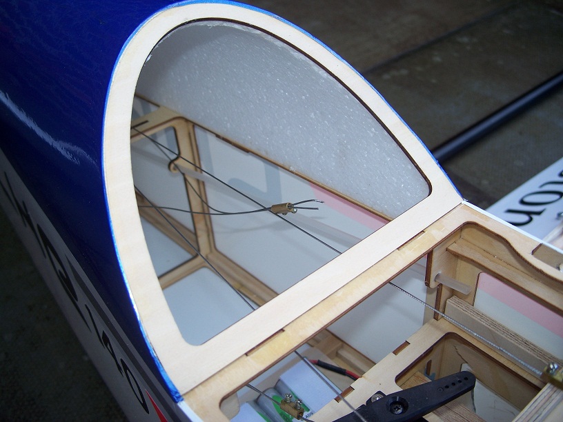
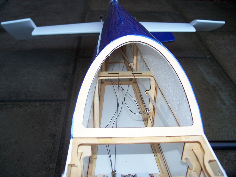
The reason for this unplanned meeting with a tree was confirmed once we got back to the pits area. I removed the canopy to find the closed loop elevator control line snapped clean through at the up elevator side of the servo horn (see pic). This wasn’t a result of the impact as the stabiliser/elevator surfaces were pretty much undamaged and explained the lack of control, this hopefully ruled out pilot error and radio problem.
I took into account if the model was worth repairing, I decided to go for it as it is such an nice model to fly and I like a challenge, it will also allow me to finish the model in a colour scheme which I’ve thinking about for a while.
Right, let’s get started. First off was to remove all the radio gear, engine and now very second hand covering etc. to assess airframe damage under the skin sort of speak!
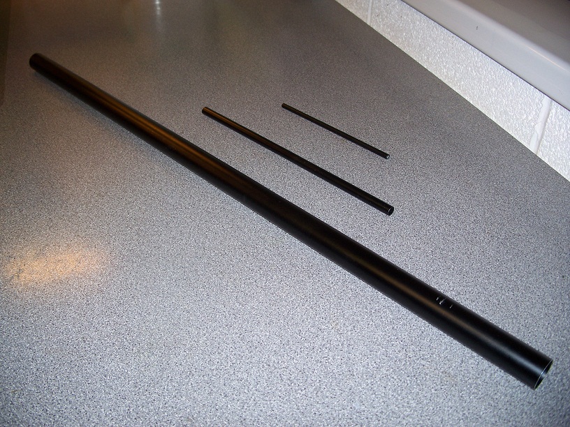
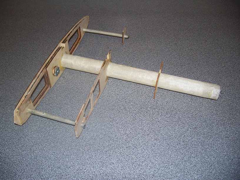
After removing all of the covering it was time to start repairing, first up was the main wing joining tube and the two smaller incidence locating tubes for the stabiliser, these were all bent a few degrees out of alignment, a few minutes on the fly press had them all sorted serviceable again.
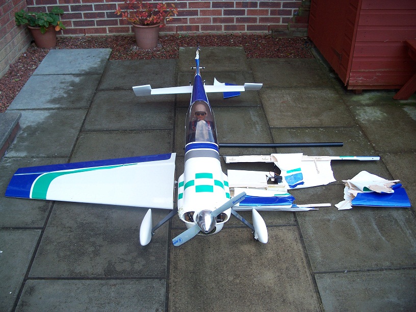
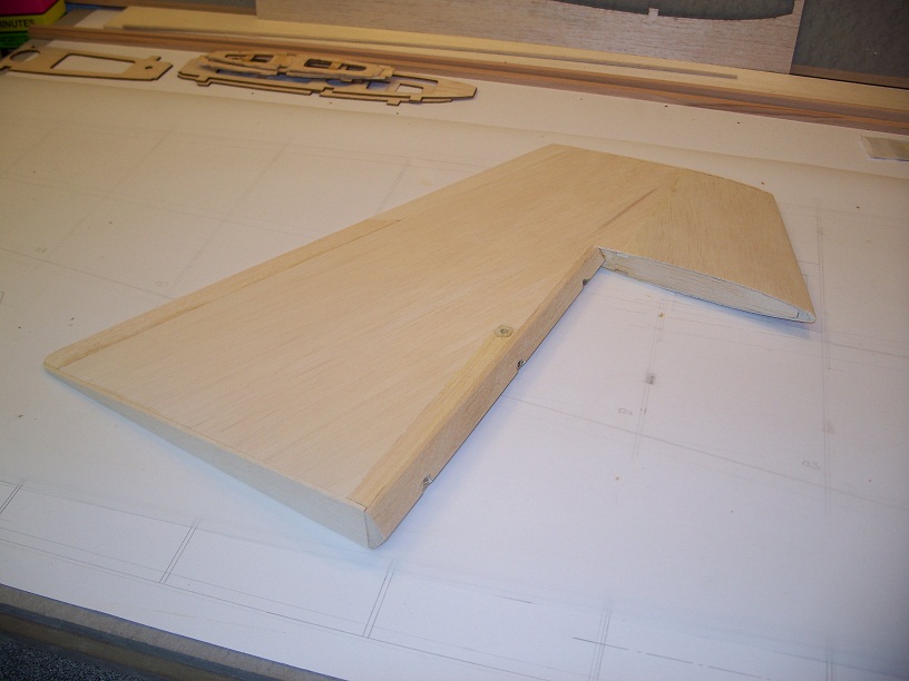
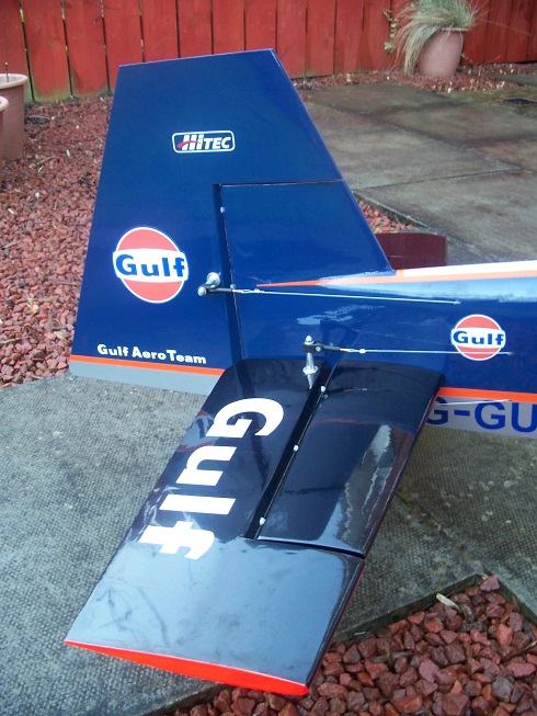
Next up was the rudder, as you can see from the first photo the top was taken clean off at the internal corner, which looked a very weak area anyway. The rudder was originally made with an open structure rear section which never felt very sturdy so I took the decision to fully sheet it using 1.6mm soft balsa sheet, this has resulted in good strong component for minimal weight gain, you can see from the photo.
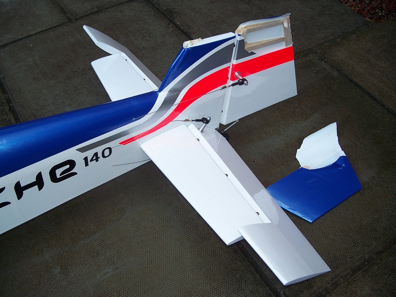
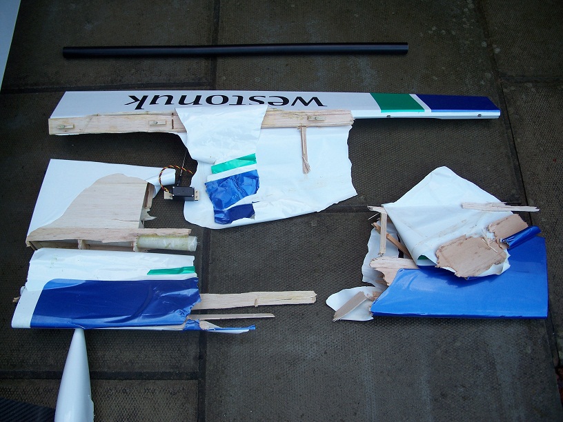
Following on from the rudder I turned attention to the left/port wing which was all but destroyed (first photo). The strange thing about it was that the aileron completely came away from the main part of the wing and was found hanging from the top of the tree the model landed in with not a mark on it, but most of the rear spar still attached! I set to work to see how much was reusable, not much in the end. All that was worth using was rib no 1, half of rib 2, GRP tube sleeve and rib 10 wing tip, not a lot to go on really!(see pic)
First off, I had to determine the wing rib section profile so I could replace all of the missing ribs. The wing has a symmetrical section profile with uniform taper down to the tip (no wash out). To achieve the correct profile of rib I traced around the intact root rib (R1), scanned the image on to a P.C. and then imported it into a software program which allowed me to size and scale each rib to the required dimensions before each was able to be laser cut.
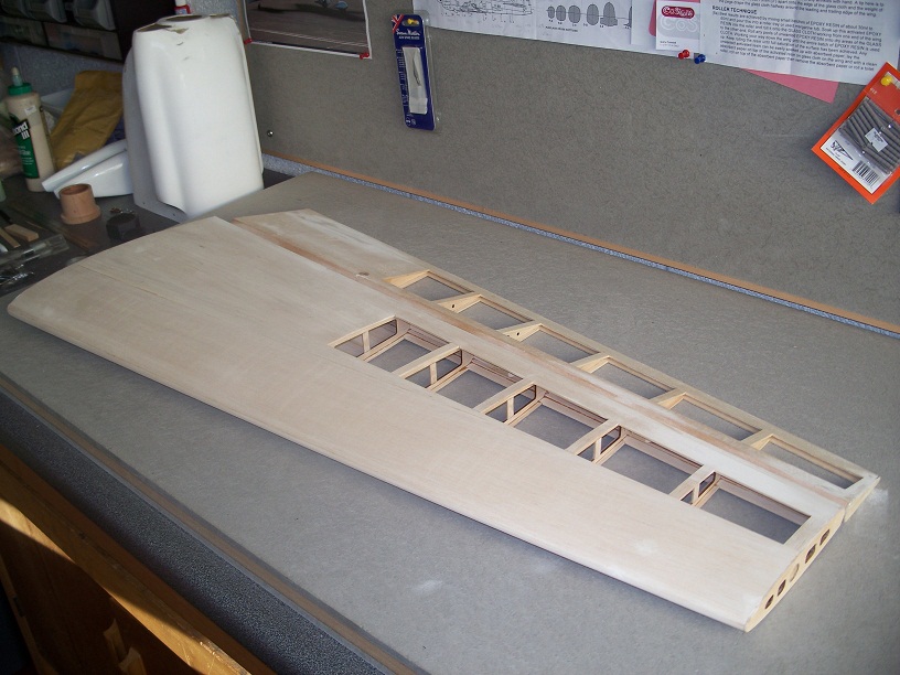
Whilst it took a few days to sort out the new ribs I produced a 1:1 scale drawing of the wing using the other intact one, as a template to give a plan in order build the new one over. Once I had the entire set of new ribs laser cut it was time to start building!! The construction started out by laying out the top central spar raised 2mm off the plan to take into account of the top sheeting as the wing is constructed upside down.
There isn’t any dihedral angle set into the root rib but this is achieved by the rising taper of the ribs getting smaller towards the tip with the top flat at 0 degree plain giving a 4 degree rise across the bottom of the ribs.
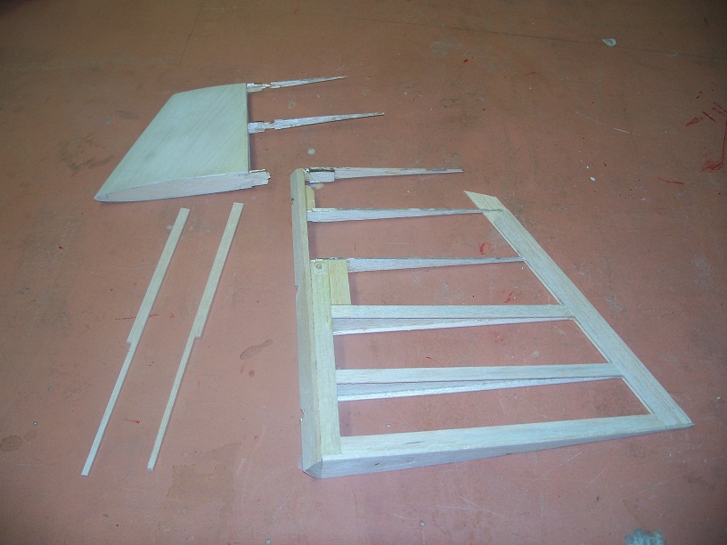
The ribs and wing tube sleeve were then glued to the top spar and then the bottom spar glued in place, once completed the leading edge and rear/hinge spar were glued in place to the stage shown in the next photo.
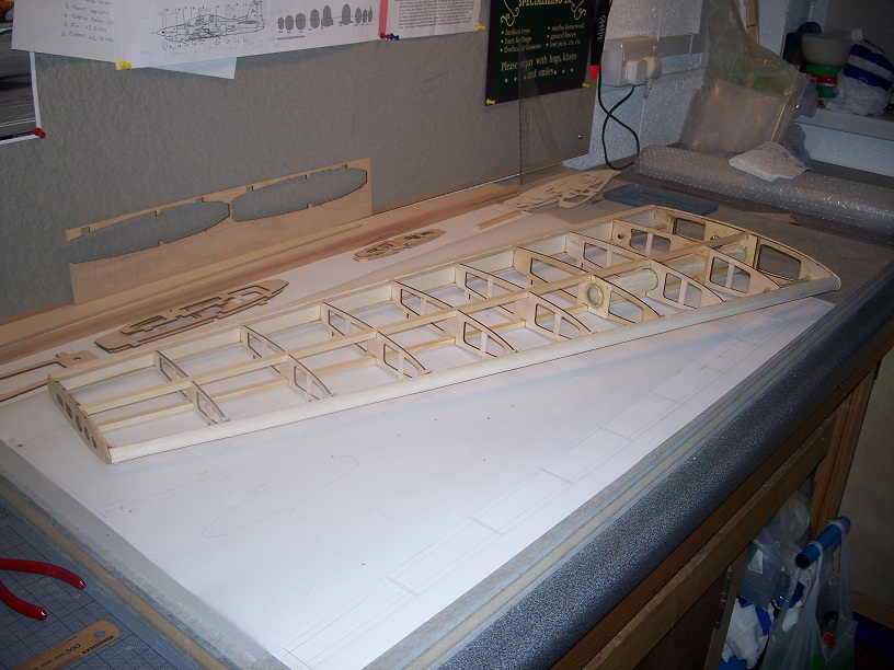
The next step was to part sheet the wing with 2mm balsa leaving some open structure to save a bit of unwanted weight; I was also amazed how the outer sheeting stiffened the whole wing over its entire length, before the open structure was quite flexible. Hinge points were predrilled at this stage to ensure an accurate match, as there are no fewer than six Robart hinges holding onto the aileron. The picture below shows the completed port wing almost ready for covering.
After the port wing was completed I turned attention to the starboard wing which needed a bit of work, this included re-sheeting some damaged areas and cleaning up of the leading edge which had succumbed to the contact with tree branches, also new hinge points were drilled.
Next up were the rear stabiliser and elevator, these also need a touch of remedial work, which included strengthening up the mounting points which fix onto the fuselage sides and a general work over to repair any dings or knocks which they’ve received during the crash. Rudder, stabiliser and elevator now ready for covering.
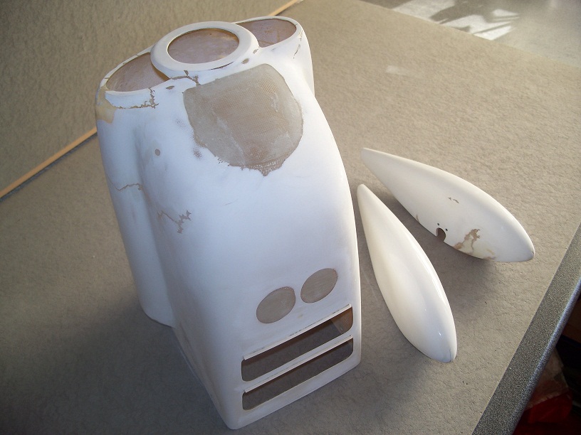
Whilst working on the previous parts of the model I got started on some of the GRP components, namely the cowl and spats, these didn’t escape the impact. The main cowl damage resulted more from the propeller breaking up as it ploughed its way through branches, cutting and cracking the cowl as it did so. The spats mainly suffered damage to their mounting points and around the centre join of the moulding.
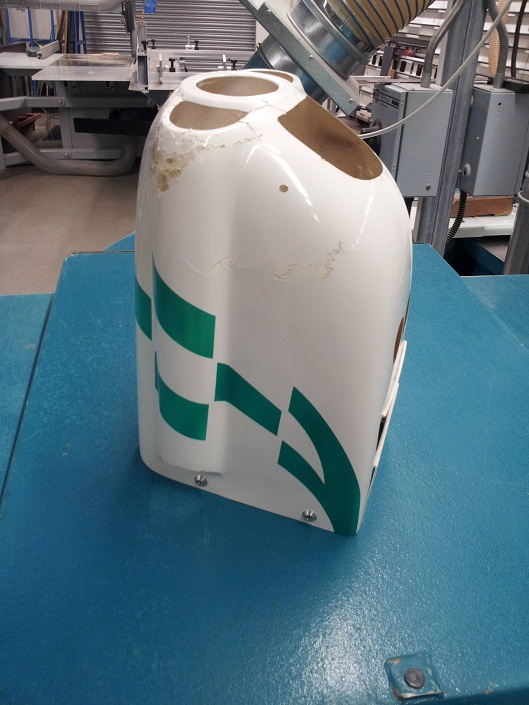
This extra glass fibre work didn’t pose much of a problem, I needed to rework the front intake hole as a different size engine was going to be fitted (NGH 35cc). The front carburettor of this engine doesn’t protrude as far forward so the clearance hole can be closed up and reshaped to provide cleaner direct air flow to the cylinder of the engine, also the exhaust outlets exit in a different position.
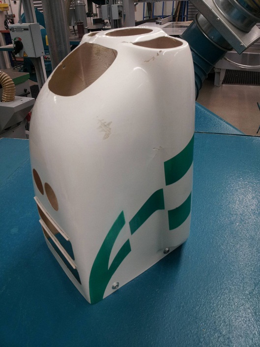
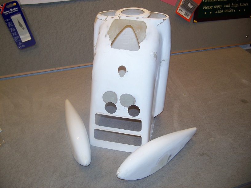
To repair and fill in the unwanted open areas I used a combination of 100gm and 200gm glass cloth in conjunction with an epoxy resin supplied by Bucks Composites. This resin is really easy to use as it has a low viscosity and long working pot life, this also allows you to take your time to work the cloth into compound surfaces. The first picture below shows the cowl and spats finished ready to test fit to the model, prior to cutting out the new apertures, next picture shows cowl with all intake and air exhaust holes cut out along with spark plug clearance slot.
After a little thought regarding the fuel tank arrangement I decided to fit a Dubro 16oz (473cc) tank. I was never very happy with the type supplied with the model as it was oval in shape and didn’t really fit the area for which it was intended without lots of foam holding it in place. Now having learned to use Adobe Illustrator recently and having access to a Laser cutter, designing and making parts is no longer a problem, so I designed a cradle for the new tank which would allow me to position it further back in the model right up to the wing tube, much closer to the C of G.
This more rearward positioning will produce a less pronounced trim change from full to empty tank. Petrol engines don’t suffer the same a glow engines with regard to tank position as the fuel is pumped by the carburettor.
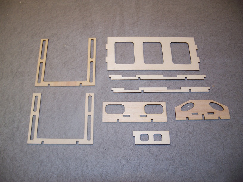
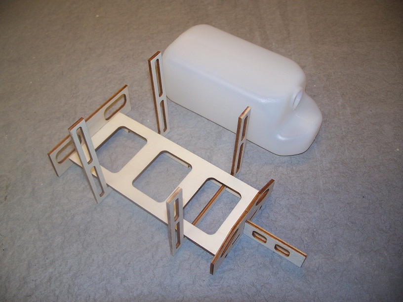
Next stage was to install the fuel tank support frame within the fuselage, this was a little tricky as it had to be fitted in order of sequence working from the front and rear of the tank area. The tank now sits much further back in the airframe which should reduce the models pitch change throughout a flight.
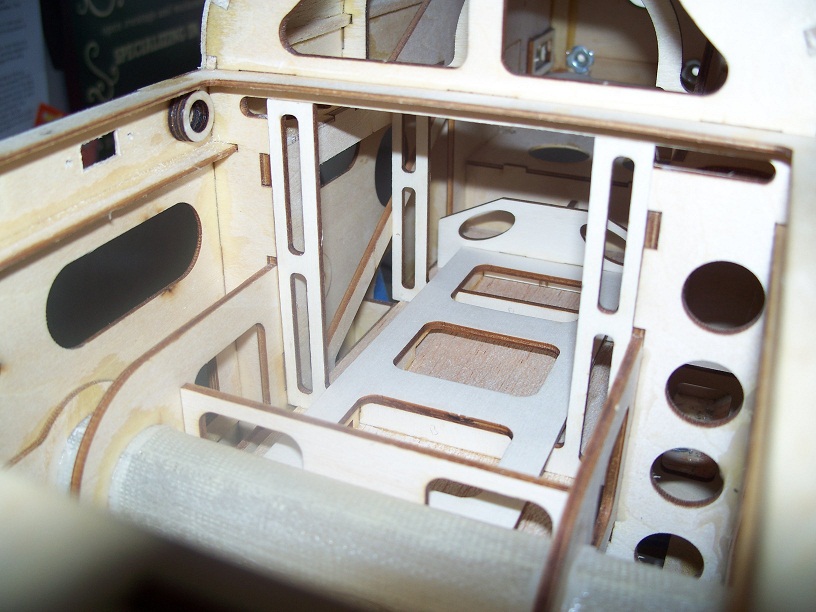
Since I’d made use of the laser cutter to make the tank support parts, I decided to re-make the Ignition battery tray which is located behind the pipe tunnel. This was relatively straight forward to install as there’s not much framework around it.
The final thing on the fuselage to do before covering was to fully fuel proof the engine bay area, this was done using gloss Aerocoat, applied by brush.
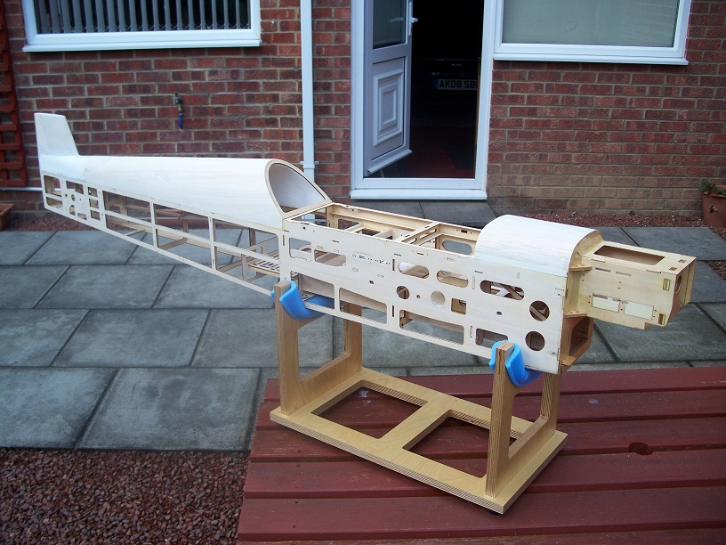
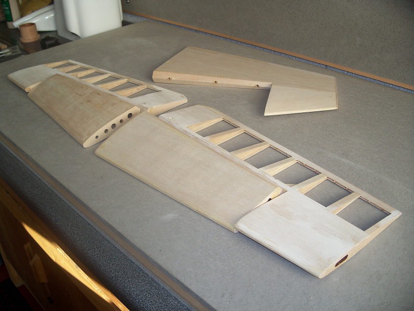
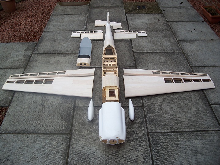
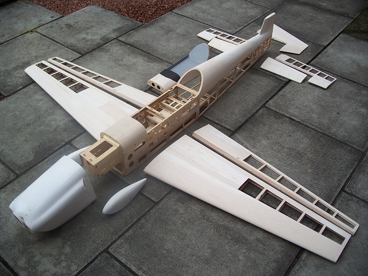
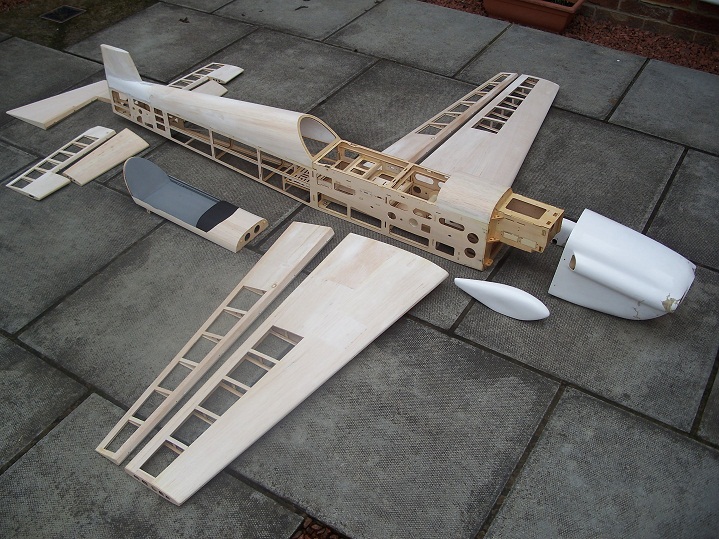
The following few pictures show all of the model’s airframe components in ‘plan situ’ prior to covering and painting.
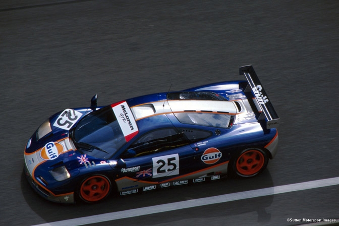
The advantage of starting from this blank canvas means that I was able to design a completely new colour scheme. I’ve always been a fan of the Gulf Oil livery as used by the 1970’s Porsche 917 and the more recent Mclaren GTR1 of the mid 1990’s. After long consideration and the choice of covering colours available I decided to go with a similar scheme to the 1995 Mclaren GTR1, using Dark Blue, Silver and Orange, this colour combination also allows for a good contrast between the upper and lower surfaces. Along with covering I’ve also had to design and make my own decals to compliment the unique design.
The picture below shows a Mclaren GTR1 in the colour scheme of which has given me the inspiration to finish the model.
It’s been a while since my last update, covering the model here and there when I’ve a few spare minutes seems to have taken an age. The photographs below show an interim update of progress.
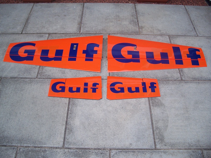
Top side of wings and stabilisers/elevators with decals applied.
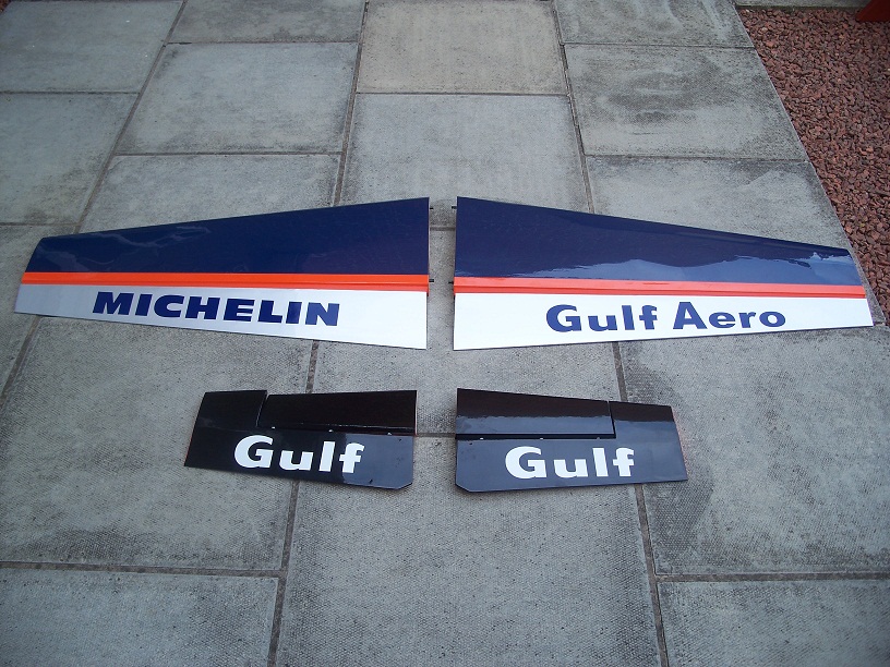
Underside of wings and stabilisers/elevators with decals applied.
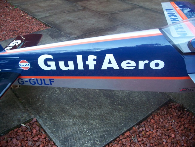
Side elevations of Fuselage sides, not all decals are applied at this stage. I’m still painting the cowl to match the fuselage colour scheme and this will have a bearing on where decals are placed.
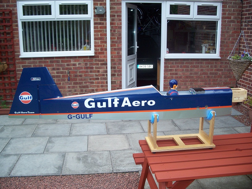
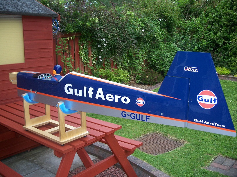
The model all seems to coming together, the major items to finish are the cowl, spats and fitting the canopy. Once these items are complete it will just be a case of installing the new engine which I’ve pre-run in on a test stand and fitting out of all the servos and linkages.
The next items to tackle were the wheel spats and cowl. Previously in the rebuild I’d spent time repairing these items due to the crash damage. This meant strengthening some areas (I find so many times cloth that hasn’t been wetted out properly and stuck down correctly, especially around the joins in the wheel spats) and filling in some unwanted holes.
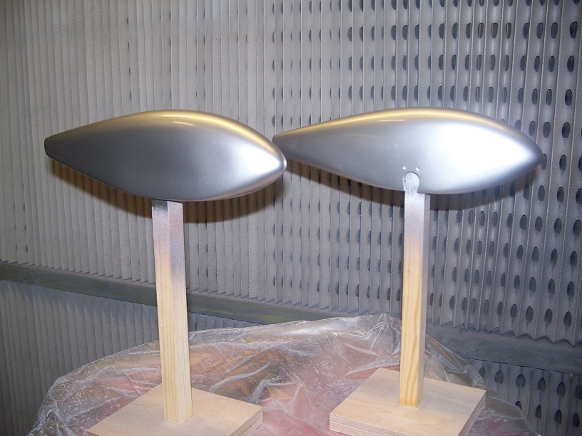
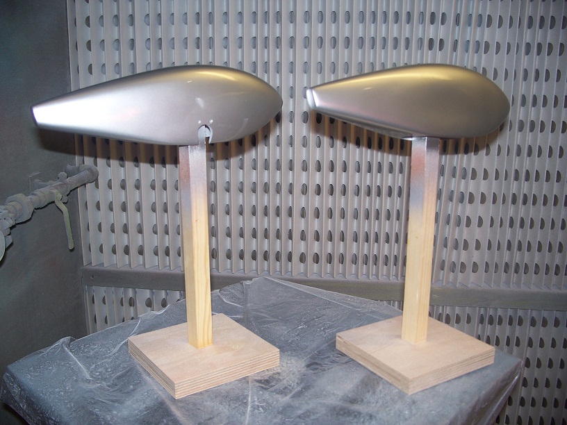
First off were the spats. Starting with the glass fibre finish, this was rubbed down with 400 grit wet and dry and then sprayed with a coat of Grey cellulose primer to highlight the surface finish and rubbed down again. Next, another coat of primer, rubbed down and on with the colour base coat of Silver, this was applied twice to give some depth of colour and then on with the clear top coat to give the final gloss finish and fuel proof. I used KlassKote 2 part epoxy gloss for the top coat and would fully recommend using it to anyone, really easy to use and gives a tough glass glossy finish, without the nasties of 2K paint.
The cowl was prepared and painted in exactly the same way as the spats but took a good time longer, as 3 colours were used, involving masking off and covering previously painted areas. I used the sequence of light to dark applying the colours, Silver, Orange and finally Blue, which is the general rule as not to use loads of paint and adding unnecessary weight. Once I was happy with all of the colours the whole cowl was sprayed with the clear coat. This really brought the cowl to life and compliments the Ora-Cover film finish.
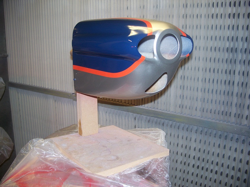
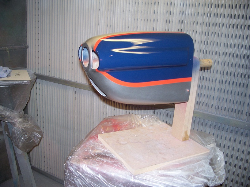
As you can see from the previous pictures, it’s a good idea to make some sort of stand to hold/fix the item to be painted. This avoids unnecessary handling (which can affect the paint finish due to greasy finger prints etc.) and allows you all-round access of the component. The stand I’d made for the cowl allowed me to rotate the part so I was always spraying from the side at a perpendicular angle to give an even finish.
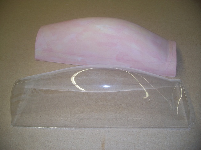
Once all the painting was complete, it was now time to start assembling the model after what has seemed an age, but it has been worth it. As the assembly was taking place I found that a new canopy was needed due to crash damage, along with a new composite undercarriage.
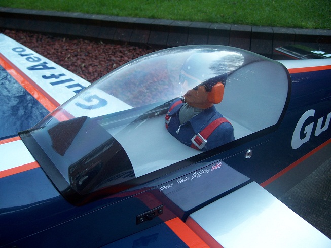
I made a mould of the canopy shape from a model board material and had this vacuum formed from clear P.E.T. plastic, it took a few goes but got a reasonable result in the end.
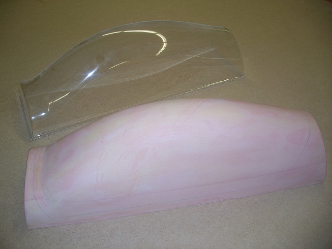
This was trimmed down to size and spray painted using Black base coat to give a canopy frame edge.
Regarding the undercarriage, the one that was fitted was fine but wasn’t of the same size and profile as the original. I took this opportunity to mould a new one to the correct size and shape as supplied with the model. Making a composite U/C is a project is itself so I’ll cover this at a later date, with regard to materials and processes involved.
Following, are a number of pictures of the completed model almost ready to fly.
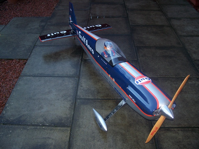
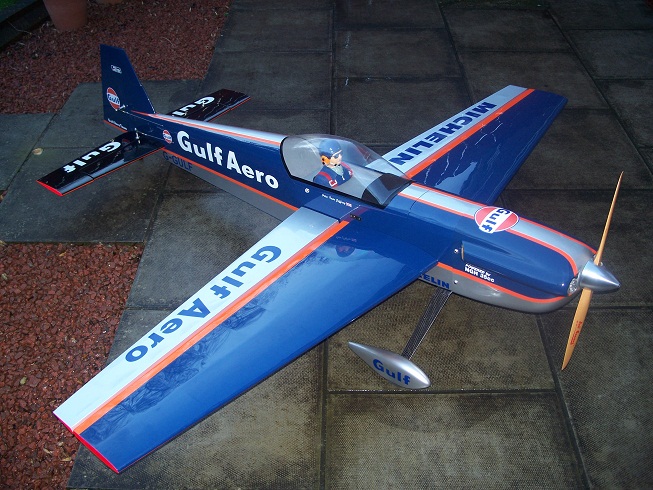
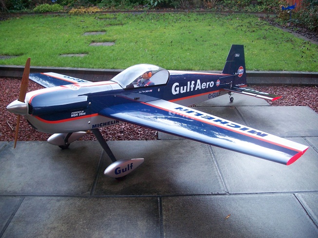
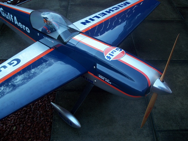
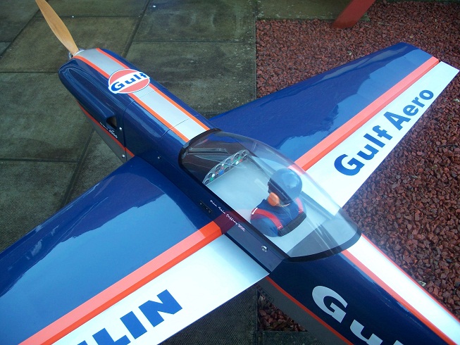
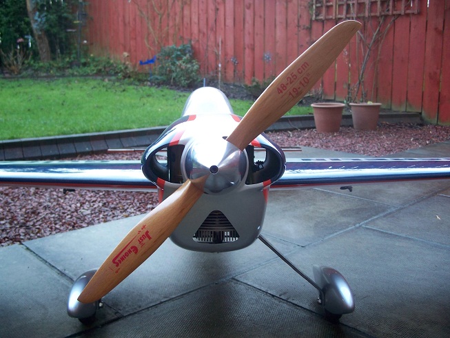
All that is needed now is to balance the model at the correct point. I’ll balance it near the front of its intended range for the first few flights to get a handle on the model, as it has a setting range of between 60mm. This is due to the model being fully 3D capable if the intention was to fly it this way.
Prior to flight I’ll do the obligatory range check (including the fail safe mode) with the engine running, and number of airframe/engine checks before taxi running along the strip.
This concludes the re-build of the Capiche, I hope it’s be interesting and informative. I’ll include some flying shots of the model in due course.